- Posts: 469
- Thank you received: 63

ACMOC Membership Benefits
- FREE quarterly magazine filled with content about antique Caterpillar machines
- FREE classified listings
- ACMOC store discounts and specials
- Full Bulletin Board Access
- Marketplace (For Sale/Wanted)
- Technical Library
- Post attachments
$44 /year ELECTRONIC
$60 /year USA
$77 /year International
- Forum
- Antique Caterpillar Machinery Owners Club
- DISCUSSION
- 944 D330 Turbo oil leak and injection pump question
944 D330 Turbo oil leak and injection pump question
4 years 6 months ago #213330
by PhilC
944A - Machine SN 43A2589 Engine SN 90A284
955K- Machine SN 71J3772 Engine SN 83Z0704
D6 SN's 4R732sp, 5R2724, 5R4832
D8 SN's 15A1254, 15A2287, 15A2723
944 D330 Turbo oil leak and injection pump question was created by PhilC
Hello All
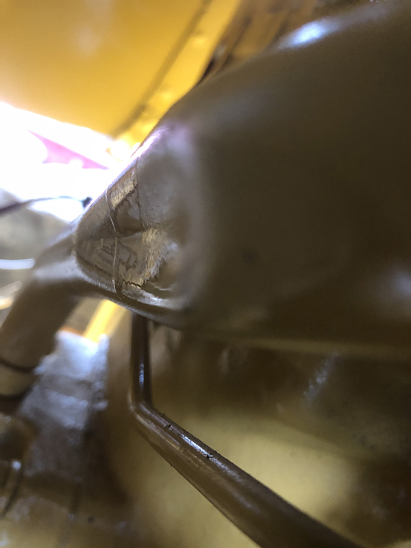
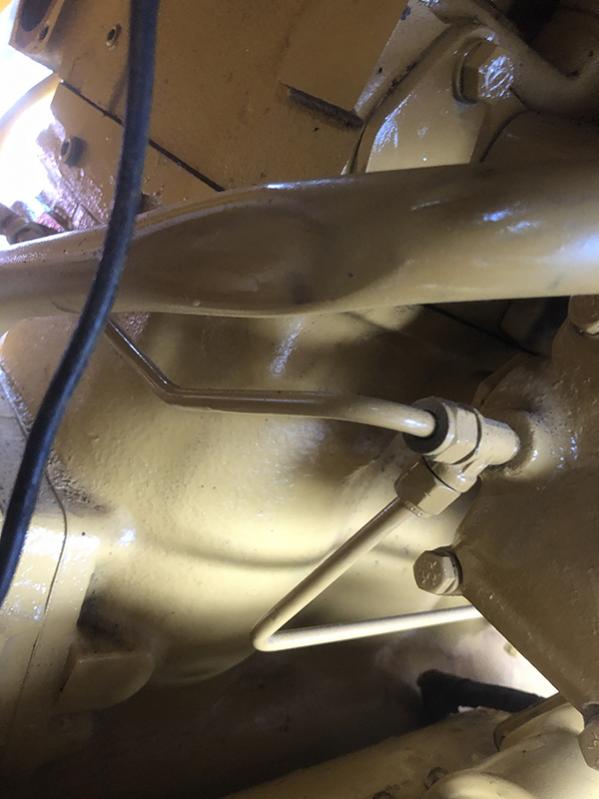
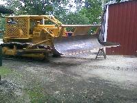
I have finally gotten my 944 going with the replacement D330 engine. There is an oil leak on the exhaust side of the turbo that is causing it to blow smoke. When I assembled the engine there was some damage in the form of a dent to the drain line from the turbo to the sump. I did not think it was bad enough to cause problems but now I am not so sure. Most turbo repair shops say the most likely cause of leaking turbos is the drain line is too small or blocked. I would say the damage to mine would reduce it capacity by about 30%. Would that be sufficient to cause the turbo to leak oil?
When I got the engine the turbo would not turn, so I pulled the exhaust side off and cleaned it up. The exhaust side had corroded enough to lock the turbo from turning. Once it was cleaned up and reassembled the shaft turned fine and the blades did not touch the housing.
I am thinking about pulling the drain off and cutting out the crushed section and repairing it to see if it stops the oil leak.
Another issue I have is it idles way too high and adjusting the idle screw on top of the injector pump makes no difference. I have had the injector pumps out and I think I got them timed correctly when reinstalled but if one was a tooth out would it cause this problem? If one pump is a tooth out would there be other symptoms? The engine seems to rev fine and responds to pedal changes as expected.
I am also concerned that both issues may be linked and a small amount of oil is leaking into the intake side but the engine rpms are quite controllable by the accelerator and it shuts down fine.
Regards
Phil
944A - Machine SN 43A2589 Engine SN 90A284
955K- Machine SN 71J3772 Engine SN 83Z0704
D6 SN's 4R732sp, 5R2724, 5R4832
D8 SN's 15A1254, 15A2287, 15A2723
Please Log in or Create an account to join the conversation.
- Old Magnet
-

- Offline
- Platinum Boarder
- Member
Less
More
- Posts: 16175
- Thank you received: 504
4 years 6 months ago #213339
by Old Magnet
Replied by Old Magnet on topic 944 D330 Turbo oil leak and injection pump question
That's a pretty good ding in the drain line, pretty restrictive for a gravity flow. I'd definitely fix or replace.
A tooth off with an injection pump can go either way, to lean one way, to rich the other with rich affecting the idle speed more.
Is this that 3Xxxxx engine if I recall right, should be new enough to get a replacement line.
A tooth off with an injection pump can go either way, to lean one way, to rich the other with rich affecting the idle speed more.
Is this that 3Xxxxx engine if I recall right, should be new enough to get a replacement line.
Please Log in or Create an account to join the conversation.
4 years 6 months ago #213344
by PhilC
944A - Machine SN 43A2589 Engine SN 90A284
955K- Machine SN 71J3772 Engine SN 83Z0704
D6 SN's 4R732sp, 5R2724, 5R4832
D8 SN's 15A1254, 15A2287, 15A2723
Replied by PhilC on topic 944 D330 Turbo oil leak and injection pump question
Hello OM
No this is the 90A284 engine out of a 950 loader that I am fitting into my 944. I will repair the drain line and see what happens. 2S3108 is the part number and it shows up as Indirect Replacement Available which means no longer available.
So the idle speed is high but smooth and the engine will shut down cleanly. I assumed if one was out on the rack then the engine idle would be rough and it would be a rough shut down as one cylinder would be still firing.
Regards
Phil
944A - Machine SN 43A2589 Engine SN 90A284
955K- Machine SN 71J3772 Engine SN 83Z0704
D6 SN's 4R732sp, 5R2724, 5R4832
D8 SN's 15A1254, 15A2287, 15A2723
Please Log in or Create an account to join the conversation.
4 years 6 months ago #213350
by Rome K/G
Replied by Rome K/G on topic 944 D330 Turbo oil leak and injection pump question
Swantrax in Hazelmere Western Aus. shows having one and some here in the US listed through Machinery Trader Parts. +61 8 6280 2110
Please Log in or Create an account to join the conversation.
4 years 6 months ago #213355
by edb
Replied by edb on topic Fast Low Idle
Hi Team,
I too believe you have enough drain line restriction to cause a backup oil oil in the turbo.
If you cannot get anew tube I would scribe a line along the axis of the tube so as to re-orientate any bends, cut the tube through the middle of the ding and work from each end on the half ding length to panel beat ot the ding and then reweld being sure to orientate the scribe lines.
If a injection pump element quadrant gear was one tooth advanced or retarded you would have one cylinder acting as described by PhilC above.
For the fast idle I would first disconnect the Gov. Control Rod from the Gov. Control Lever at the Inj. Pump and see if the linkage needs lengthening. Then check and see you can still get to High idle--Full Gov. position.
There may be a difference in the Gov Control lever lengths between the two engines that Could change the linkage ratios enough to cause a shortened stroke condition/rotation angle of the Gov. Control Shaft.
If your Gov Control lever is splined to the Gov. control shaft you may only need to re-orientate the Gov. control lever a spline or so the get within range
I seem to recall there maybe a stop bolt that can limit the accelerator pedal angle downwards so to not over-stress the linkage within the Governor--maybe 1/8" clearance when the pedal is lightly pushed down by hand. It is located up under said pedal at the operators station, also seem to recall that the said pedal comes to a fairly vertical position when it is in the Shut Off position.
Cheers,
Eddie B.
Please Log in or Create an account to join the conversation.
4 years 6 months ago #213373
by PhilC
944A - Machine SN 43A2589 Engine SN 90A284
955K- Machine SN 71J3772 Engine SN 83Z0704
D6 SN's 4R732sp, 5R2724, 5R4832
D8 SN's 15A1254, 15A2287, 15A2723
Replied by PhilC on topic 944 D330 Turbo oil leak and injection pump question
Hello All
I thought of a few different ways to fix the dent and in the end I took the tube and capped both ends, hooked it up to a compressor and heated the dent until it popped out. I refitted it this afternoon and ran the engine and it did seem to fix the problem. When I removed the tube I remembered the reason I thought it would not matter as the tube itself is 7/8"ID but the end that goes into the flywheel housing has a fitting for an o-ring that reduces the diameter to 5/8"ID.
Eddie the Gov Control lever is keyed to the shaft so it can't be indexed but it would not help anyway. The accelerator linkage is free to move in either direction. I could not find a stop bolt. The governor has the low oil pressure lock but it seems to release fine. I think I will have to remove the end cover and see if I can see anything that would cause the high idle. I don't think the low idle adjustment screw was touching the linkage inside as it was very free to move in either direction and the lever did not move at all.
Also would the high idle cause the diesel knock to sound worse than it should?
Does anyone know the replacement part number for the 7m6001 tachometer?
Regards
Phil
944A - Machine SN 43A2589 Engine SN 90A284
955K- Machine SN 71J3772 Engine SN 83Z0704
D6 SN's 4R732sp, 5R2724, 5R4832
D8 SN's 15A1254, 15A2287, 15A2723
Please Log in or Create an account to join the conversation.
4 years 4 months ago #217673
by PhilC
944A - Machine SN 43A2589 Engine SN 90A284
955K- Machine SN 71J3772 Engine SN 83Z0704
D6 SN's 4R732sp, 5R2724, 5R4832
D8 SN's 15A1254, 15A2287, 15A2723
Replied by PhilC on topic 944 D330 Turbo oil leak and injection pump question
Hello All
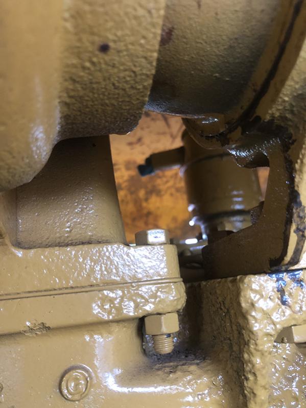
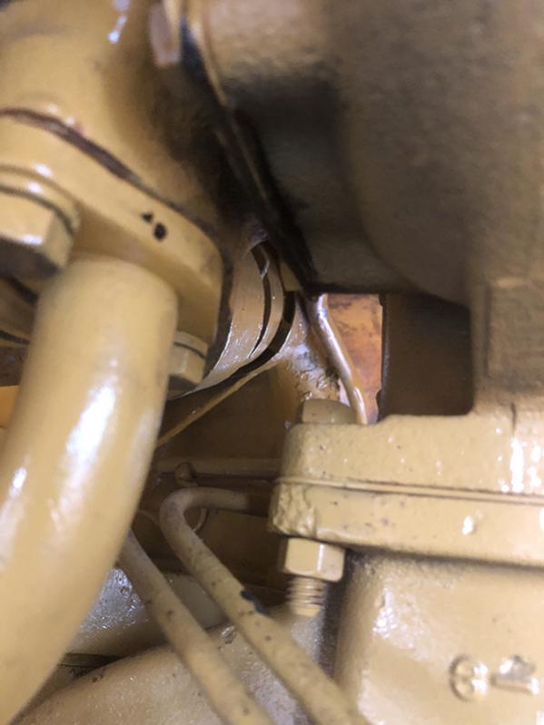
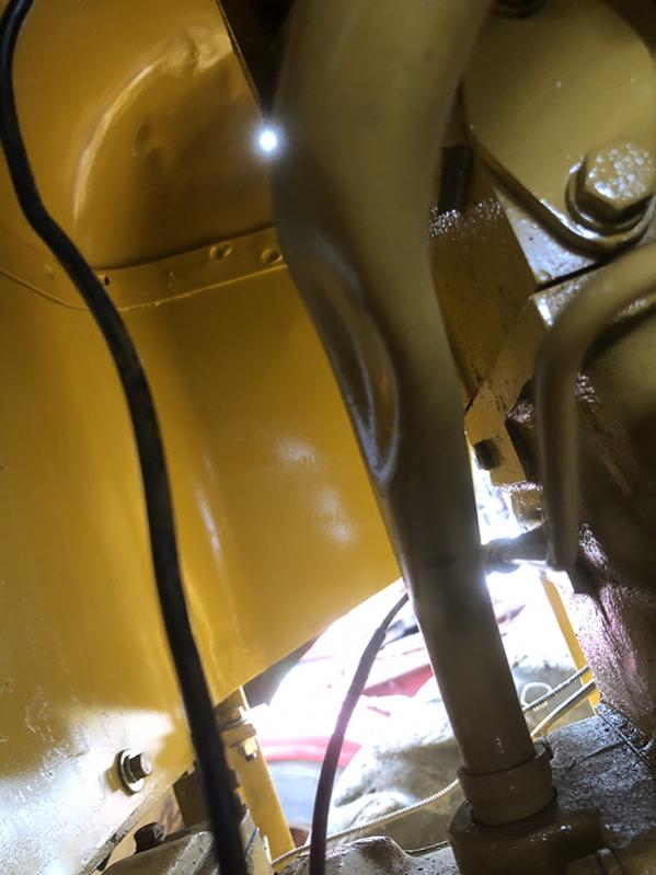
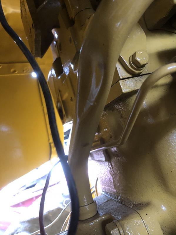
I finally got round to dismantling the governor on the 944. I think I have found the problem. It looks like when I assembled the pumps I have somehow got all four out by at least one tooth.
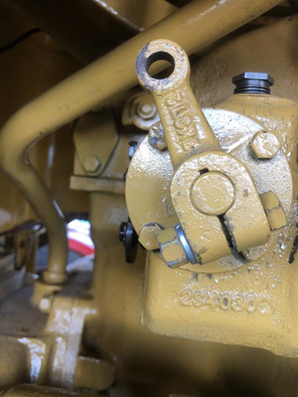
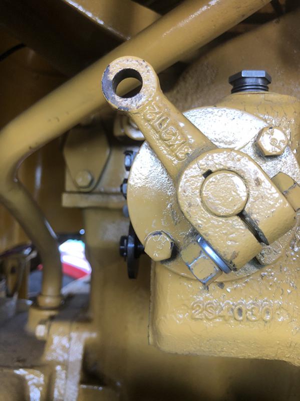
The photos show the lever movement where there is no spring resistance which I am assuming is caused by the rack being out of index. I can remove the free play by adjusting the idle adjusting screw in but that does not help with the idle. I am thinking I did not have the stop for the rack set correctly.
Does anyone think it could be something else? Before I rip all the pumps out again.
Regards
Phil
I finally got round to dismantling the governor on the 944. I think I have found the problem. It looks like when I assembled the pumps I have somehow got all four out by at least one tooth.
The photos show the lever movement where there is no spring resistance which I am assuming is caused by the rack being out of index. I can remove the free play by adjusting the idle adjusting screw in but that does not help with the idle. I am thinking I did not have the stop for the rack set correctly.
Does anyone think it could be something else? Before I rip all the pumps out again.
Regards
Phil
944A - Machine SN 43A2589 Engine SN 90A284
955K- Machine SN 71J3772 Engine SN 83Z0704
D6 SN's 4R732sp, 5R2724, 5R4832
D8 SN's 15A1254, 15A2287, 15A2723
Please Log in or Create an account to join the conversation.
4 years 4 months ago #217685
by ccjersey
D2-5J's, D6-9U's, D318 and D333 power units, 12E-99E grader, 922B & 944A wheel loaders, D330C generator set, DW20 water tanker and a bunch of Jersey cows to take care of in my spare time:D
Replied by ccjersey on topic 944 D330 Turbo oil leak and injection pump question
How did you position the rack before installing the pumps?
I built a little fixture from a bushing that would fit in the access hole after the little cover was removed and which the rack would fit inside. It had a nut welded in one end and I screwed a bolt through until the tip of it was recessed the proper dimension and locked it with a jamb nut. If I remember correctly there was some (Little) spring tension pushing back against the fixture as it was pushed home against the face of the pump housing.
I built a little fixture from a bushing that would fit in the access hole after the little cover was removed and which the rack would fit inside. It had a nut welded in one end and I screwed a bolt through until the tip of it was recessed the proper dimension and locked it with a jamb nut. If I remember correctly there was some (Little) spring tension pushing back against the fixture as it was pushed home against the face of the pump housing.
D2-5J's, D6-9U's, D318 and D333 power units, 12E-99E grader, 922B & 944A wheel loaders, D330C generator set, DW20 water tanker and a bunch of Jersey cows to take care of in my spare time:D
Please Log in or Create an account to join the conversation.
4 years 4 months ago #217749
by edb
Replied by edb on topic Rack Set Position
Hi Team,
if you had the Cat 8M0530 Gauge ( Rack micrometer), you would read 0.000 on it BUT, if using a depth mike and the Cat 1M6953 Gauge/spacer the measurement is 1" as said above.
NOW, assuming you have none of these tools, in actual fact, the rack protrudes the actual Injection Pump front mounting face (down inside the bore under the 2 bolt cover) by 0.1563" to be at Zero rack position for installing your pump elements as outlined in the scan below.
NOTE
the rack travel check dimensions in either direction (in or out) to ensure you have the pump gears aligned correctly--alas, the dimensions are for when using the Gauge as outlined--but are NOTED as being a movement of 0.312" in either direction of the Zero position to be aligned correctly.
Hope this helps.
Cheers,
Eddie B.
Please Log in or Create an account to join the conversation.
4 years 4 months ago #217841
by PhilC
I made something similar up that used the bolt hole for the cap. I thought I had the correct dimensions as per the workshop manual.
Thanks Eddie. I could not procure either the 8M0530 nor the 1M6953 so I made my own. I thought I had it all worked out. I do have a depth micrometer somewhere but I cannot find it.
I only get about an hour to work on the 944 each afternoon and I spent that hour today looking for the jig I had made. I hope to have another look at it tomorrow.
Regards
Phil
944A - Machine SN 43A2589 Engine SN 90A284
955K- Machine SN 71J3772 Engine SN 83Z0704
D6 SN's 4R732sp, 5R2724, 5R4832
D8 SN's 15A1254, 15A2287, 15A2723
Replied by PhilC on topic 944 D330 Turbo oil leak and injection pump question
How did you position the rack before installing the pumps?
I built a little fixture from a bushing that would fit in the access hole after the little cover was removed and which the rack would fit inside. It had a nut welded in one end and I screwed a bolt through until the tip of it was recessed the proper dimension and locked it with a jamb nut. If I remember correctly there was some (Little) spring tension pushing back against the fixture as it was pushed home against the face of the pump housing.
I made something similar up that used the bolt hole for the cap. I thought I had the correct dimensions as per the workshop manual.
Hi Team,
if you had the Cat 8M0530 Gauge ( Rack micrometer), you would read 0.000 on it BUT, if using a depth mike and the Cat 1M6953 Gauge/spacer the measurement is 1" as said above.
NOW, assuming you have none of these tools, in actual fact, the rack protrudes the actual Injection Pump front mounting face (down inside the bore under the 2 bolt cover) by 0.1563" to be at Zero rack position for installing your pump elements as outlined in the scan below.
NOTE
the rack travel check dimensions in either direction (in or out) to ensure you have the pump gears aligned correctly--alas, the dimensions are for when using the Gauge as outlined--but are NOTED as being a movement of 0.312" in either direction of the Zero position to be aligned correctly.
Hope this helps.
Cheers,
Eddie B.
Thanks Eddie. I could not procure either the 8M0530 nor the 1M6953 so I made my own. I thought I had it all worked out. I do have a depth micrometer somewhere but I cannot find it.
I only get about an hour to work on the 944 each afternoon and I spent that hour today looking for the jig I had made. I hope to have another look at it tomorrow.
Regards
Phil
944A - Machine SN 43A2589 Engine SN 90A284
955K- Machine SN 71J3772 Engine SN 83Z0704
D6 SN's 4R732sp, 5R2724, 5R4832
D8 SN's 15A1254, 15A2287, 15A2723
Please Log in or Create an account to join the conversation.
- Forum
- Antique Caterpillar Machinery Owners Club
- DISCUSSION
- 944 D330 Turbo oil leak and injection pump question
Time to create page: 0.440 seconds
ACMOC
Antique Caterpillar Machinery Owners Club
P.O. Box 9301
Peoria, IL 61612
(309) 691-5002
cat@acmoc.org
Become a Member!
"I became a member recently because the wealth of knowledge here is priceless."
- Chris R
"I also joined a year ago. had been on here a couple of times as a non-member and found the info very helpful so I got a one year subscription (not very expensive at all) to try it out. I really like all the resources on here so I just got a three year. I think its a very small price for what you can get out of this site."
- Jason N